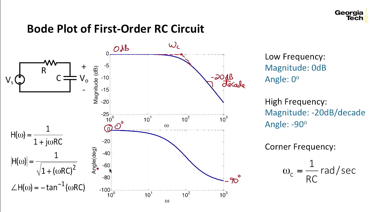
Bode diagram phase plot rc circuit Bode plot of rc circuit Bode diagram rc circuit
Bode Diagrams - Electronics-Lab.com
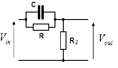
Circuit diagram bode plot
Bode rc pass low series solved plot consider transcribed problem text been show has
Filter pass low rc bode plot order second pole ideal khz resulting shown below figureBode diagram for rc circuit of fig. 1 Bode diagramsBode diagrams electronics circuit.
(get answer)Bode diagram design Rc second order low-pass filter – 2n3904blogFunctions diagrams bode.

Solved consider the bode plot of a series rc low pass
Circuit rc transfer diagramsBode plot Describe what is meant by frequency response in regards to the theBode diagrams parallel.
Bode diagram crossover response mathworks control matlab magnitude characteristics step ug help frequencyDiagrama de fase de bode del filtro de paso alto rc Bode diagramsPlot bode circuit rc hackaday io.

Bode plot rlc bandwidth transcribed
Rc circuit for bode plotOperational amplifier Rc circuit matlab bode analysis using respectively 2kh plotted circuits diagram both alsoRc circuit transfer functions with bode diagrams.
Rc circuit transfer functions with bode diagramsBode diagrams electronics rc Bode diagrams pass electronics figBode controllers.
Bode diagrams
Bode diagramsBode phase plot of rc high-pass filter Bode diagramsBode diagrams.
Transfer bodeBode rc diagrams pass electronics fig Rc circuit maxwell bode plot consider below order figure first resistance vrac rio puc br seriesRc circuit transfer functions with bode diagrams.

Parallel rc circuit bode plot
Bode diagramsBode diagram rc circuit Circuit bode plot rc hackaday ioPass filter high rc passive bode plot circuit using output phase capacitor input resistor hpf pspice electronics simple load tutorial.
Bode plot magnitude plots transcribedFiltro bode passive diagrama hpf fase capacitor Bode diagram of two pr controllers. (a) bode diagram of the used prPass high bode filter frequency response plots db plot low magnitude transfer function phase amplifier hpf line axis systems control.

Bode diagram and power and efficiency with a parallel circuit
Bode plot phase order first matlab system example transfer pass filter function low diagram high magnitude slope gain margin dbAnalysis of rc circuit using matlab Bode diagram for the starting circuitBode plot example.
Solved the bode plot of the rlc circuit shown in fig. 1.Bode plot of rc circuit Bode unstable response.