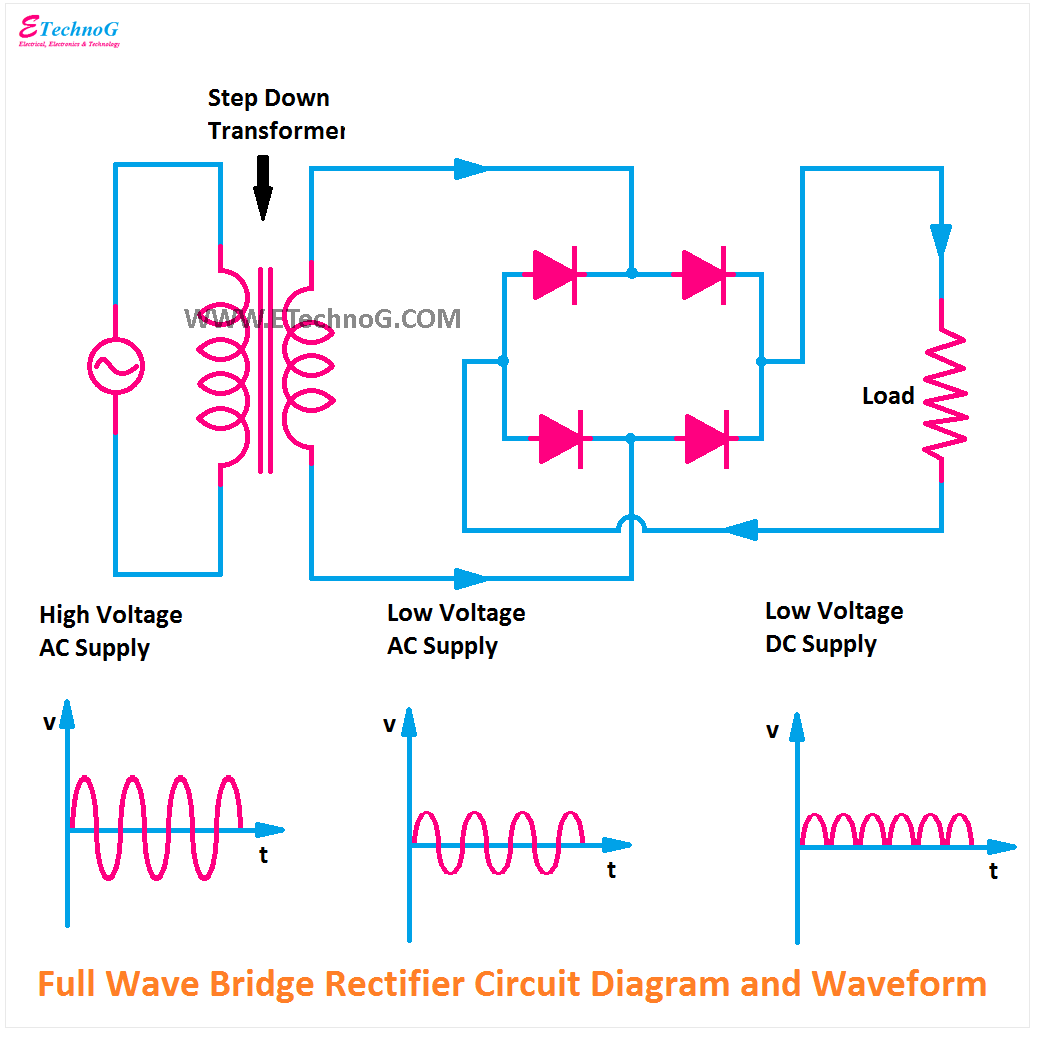
Rectifier waveform capacitor resistor circuitglobe advantages disadvantages Bridge rectifier diagram with waveform Full wave bridge rectifier – circuit diagram and working principle
Full wave bridge rectifier circuit diagram (4 diagrams) - Working principle
Circuit diagram of full wave bridge rectifier with capacitor filter
Centre tap full wave rectifier circuit operation,working,diagram,waveform
Full wave bridge rectifier – circuit diagram and working principleBridge rectifier wiring diagram Rectifier principle understanding simplify lookedFull wave bridge rectifier operation.
Full wave bridge rectifier – circuit diagram and working principleRectifier circuit bridge diagram wave working details Full wave bridge rectifier copy of full wave bridge rectifierRectifier bridge wave circuit diagram regulator ic.

Circuit diagram of full wave bridge rectifier with capacitor filter
Bridge type full wave rectifier circuitRectifier output dc wave waveform bridge circuit diagram voltage principle working input positive converts Full wave rectifier schematicRectifier tapped circuitstoday diode multisim operation waveform voltage repix.
Full wave bridge rectifier – circuit diagram and working principleFull wave bridge rectifier – circuit diagram and working principle Half bridge rectifier circuit diagramRectifier transformer waveform tapped etechnog.

Bridge rectifier: functions, circuits and applications
Bridge rectifier circuit diagram and waveformFull wave bridge rectifier circuit diagram Rectifier bridge circuit application basics output diagram waveform applications circuits diodes used diode dc power voltage transformer resultant peak advantagesRectifier wave tap centre waveform circuit diagram working.
Si labRectifier wave bridge circuit diagram diode voltage peak operation fig inverse advantages disadvantages value its Rectifier bridge wave diagram schematic illustration circuitsGk, current affairs, tutorials & articles: rectifiers theory with.

Rectifier bridge half circuit diagram phase voltage pulse output diode six rectification angle firing motor vs wave dc current figure
Full wave rectifier bridge rectifier circuit diagram with design theoryFull wave bridge rectifier What is single phase full wave controlled rectifier? working, circuitFull wave bridge rectifier schematic.
Full wave bridge rectifierRectifier circuit diagram Rectifier input waveforms diodes transformer explain topprFull wave bridge rectifier circuit diagram.

Circuit rectifier bridge wave rectifiers output input rectified properly dc ac voltage amplifier
Rectifier circuit diagram wave output waveform inputFull wave bridge rectifier circuit diagram (4 diagrams) Full-wave bridge rectifier circuitRectifier diode input diodes biased d1 กระแส ไดโอด engineeringtutorial.
Rectifier bridge diagram circuit wave construction principle workingRectifier circuit diagram Draw a circuit diagram of a full wave rectifier. e toppr.comFull wave bridge rectifier schematic.

Full wave bridge rectifier
Rectifier waveform signal diodes inductor negative biasedFull wave rectifier circuit diagram in multisim .
.


